This research proposed two types of lap-spliced intermediate hoops to address the construction challenges typically encountered with conventional intermediate hoops or stirrups used in the plastic hinge regions of beams in special moment-resisting frames. Conventional hoop configurations for reinforced concrete beams generally consist of perimeter hoops made from stirrups with seismic hooks at both ends, closed by crossties and lateral support ties or stirrups (Fig. 1), as required by design codes (ACI 318-19).
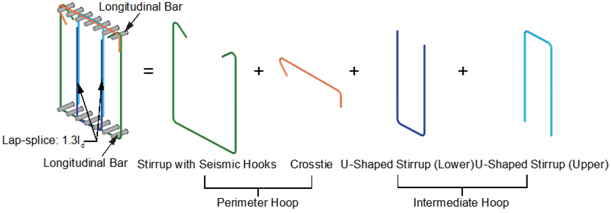
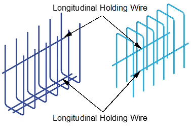
In the proposed Type 1 hoops, a set of U-bars was lap-spliced to another set of U-bars (Fig. 2(a)). These U-bars were formed by welding multiple U-bars together using longitudinal holding wires (Fig. 2(b)) made of weldable steel wire reinforcement. In the proposed Type 2 hoops, two three-dimensional stirrups were lap-spliced to form intermediate hoops (Fig. 3). The lap splice length adhered to the Class B tension lap splice requirements of ACI 318.
Three full-scale beam specimens, each with a cross-section of 700 mm × 900 mm (width × depth), were tested under lateral cyclic loading (Fig. 5). These included two specimens with the proposed lap-spliced intermediate hoops and one control specimen with conventional intermediate stirrups (Fig. 4). The tests were conducted at the National Center for Research on Earthquake Engineering, Taipei, Taiwan.
Compared to the control specimen (CH), the two specimens with lap-spliced intermediate hoops (LH1 and LH2) demonstrated superior performance under cyclic loading. The hysteresis curves (Fig. 6) revealed that LH1 and LH2 exhibited higher peak strengths and slower post-peak strength degradation compared to CH. This improved seismic performance is attributed to the effectiveness of the proposed lap-spliced intermediate hoops in restraining the buckling of longitudinal bars, outperforming conventional closed stirrups. (土木系歐昱辰教授提供)
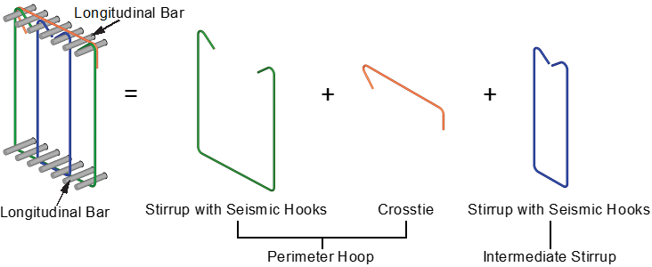
Fig. 1. Conventional hoops (CH)
(a)
(b)
Fig. 2. Proposed type one lap-spliced hoops (LH1): (a) hoop configuration, and (b) multiple U-bar set
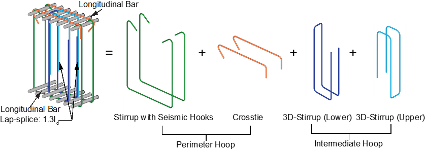
Fig. 3. Proposed type two lap-spliced hoops (LH2)
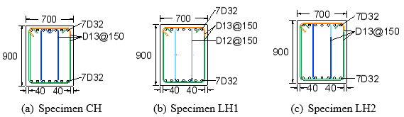
Fig. 4. Specimen cross-sections
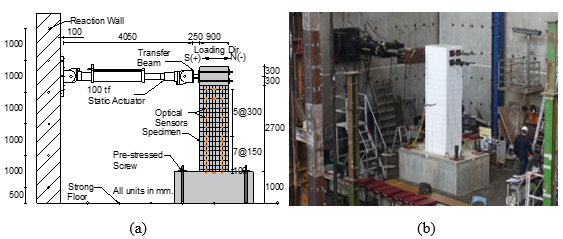
Fig. 5. (a) Test setup, and (b) Photo of the test setup
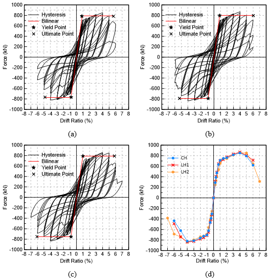
Fig. 6. Hysteresis curves of specimens: (a) CH, (b) LH1, (c) LH2, and (d) envelope responses of all specimens